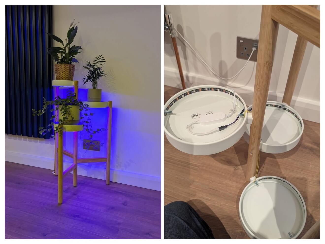
For a small home project, my son suggested adding some under lights to a plant stand we recently added to our kitchen. I figured we could do this with a cheap LED strip and it could connect to the "house" using Zigbee and Home Assistant.
All was well until I realised the plug socket nearest the plants already had it's USB port in use and only the USB-C port was available. No worries, I'll just snip the USB plug and swap in a USB-C plug. Or so I thought.
TL;DR
The USB-C breakout boards with plugs attached tend to have a ~50K resistor tied to VCC. It needs to be removed, and a 5.1K resistor tied from ground to A5.
USB-C breakout boards
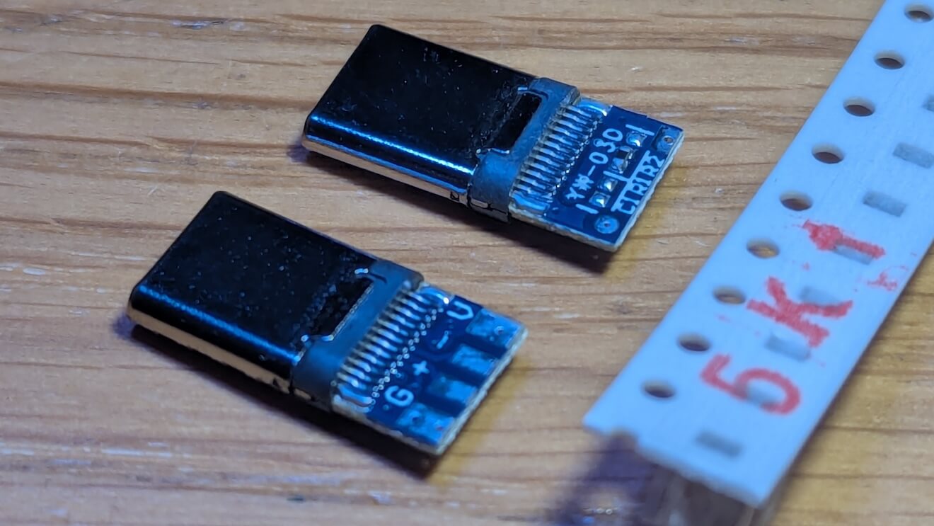
I was using these 4 pad USB-C breakouts since they're considerably easier to work with given the large solder pads for power and ground, and as I didn't need to use the data lines.
I originally snipped off the end of the regular USB plug on the LED strip and then soldered on the new USB-C port. I did a short test injecting power via my bench supply and it appeared to work.
When I did a real test by plugging it into my wall USB-C socket, absolutely nothing happened. I was quite confused (for a brief moment worried I had killed my socket - I hadn't).
I also added a USB-C voltmeter between my new plug and the wall socket and it confirmed: zero volts being delivered.
This is because USB-C is smart, but to be smart, the "host" (in my case, the wall socket) needs to ask a question of the peripheral to be sure what kind of voltage to deliver.
I had assumed if the peripheral was dumb and didn't "reply", the host was send out 5v (as it does with a traditional USB host), but apparently not (or certainly not for the case of my wall socket). Actually, if I've understood USB-C correctly, the host also needs to get confirmation that a peripheral has been inserted (and not another host).
This question and answer process is done through resistors, and possibly magic unicorns. Still, the specification is here if you're interested.
The USB-C breakout comes with a 56K resistor tied from A5 (CC) to VCC, which means it's originally suited to making a USB-C to USB 2.0 cable. Not what I need at all.
To remedy this, the resistor is removed, and a 5.1K resistor is added tying A5 to ground. Thankfully the breakout board does have a preconfigured pads to make this relatively straight forward (both for SMD or THT soldering).
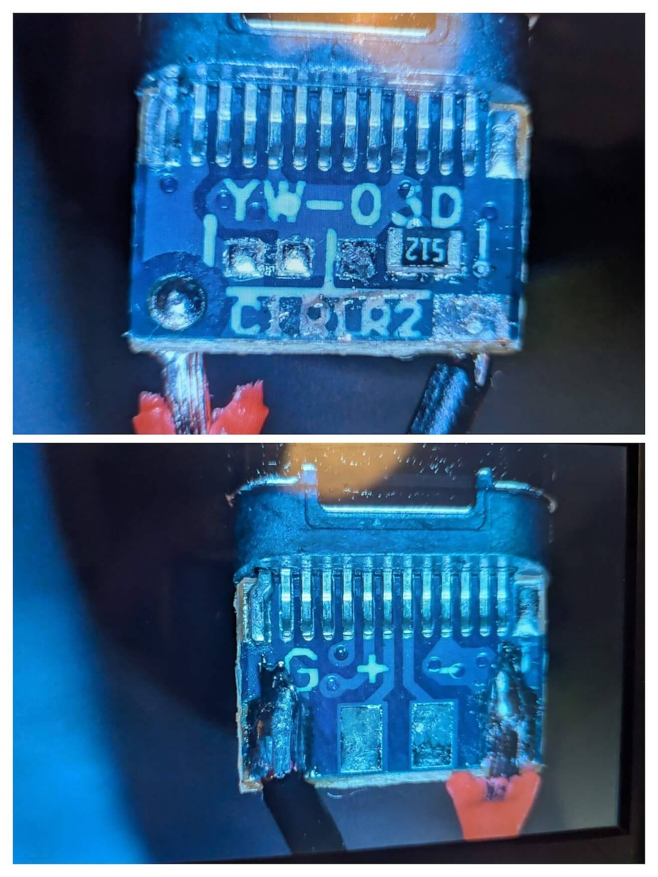
My soldering was a bit crunchy, but the resistor is now correct and when plugged in, the device now correctly pulls 5V from the wall socket.
The result, after sticking down the LED strip is now we've got some semi-fancy under plant lighting (which I promise you, looks better in real-life!):